D 629
Printed From: BMPT Forum
Category: General Discussion
Forum Name: Modelling
Forum Description: Discussion about Modelling
URL: http://www.bmpt.co.uk/forum_posts.asp?TID=499
Printed Date: 26 March 2026 at 9:53pm
Topic: D 629
Posted By: Bob Butcher
Subject: D 629
Date Posted: 12 February 2008 at 12:05pm
|
I am building a model of the above boat and have encountered a problem with deck detail. I believe there should be a section of timber which runs across the transom, mitred on the corners and runs forward up the port and starboard sides of the deck which sits on top of the top rubbing strake and consequently onto the deck by a small amount. If this is so does this timber run all the way to the prow or does it stop at certain frame number? Just inside this section of timber there is another section which copies it but this has the stanchions interspersed along it's length. Hope somebody out there can help. Bob ------------- Bob |
Replies:
Posted By: Christian
Date Posted: 12 February 2008 at 9:12pm
|
Hello Bob I presume you mean MTB 629, a Fairmile D. These boats all had an external doubler strake fitted as a result of some structural failures in extreme weather, they ran from just in front of the aft towing plates to a point just forward of the exhaust outlets, underneath the rubbing strakes (above the portholes). The thin strips on the decks between the stanchions were toe-rails, these ran all around the boat. The fitting of the doubler strakes is mentioned in LC Reynolds book MGB 658. |
Posted By: Bob Butcher
Date Posted: 15 February 2008 at 11:24am
|
Hello Christian, Thanks so much for your reply, unfortunately I could not have been clear enough in my explanation of the information I require re the Fairmile D 629. From the photograph of MTB 629 on pages 40/41 of John Lamberts book "The Fairmile D" Motor Torpedo boat there appears to be a section of timber (approx. 5" in width and 2" thick) across the stern and running forward along the starboard and portside edge of the deck and overlapping the top mahogany rubber. Am I correct in this assumption and, if so, does this timber section go to the prow and if not at which frame number forward does this section of timber stop? The thin strips between the stanchions sit a bit further in deck from the section I am querying. Any advice you can give me will be much appreciated so that I can get on with the construction of my model. Regards, Bob ------------- Bob |
Posted By: Pioneer
Date Posted: 15 February 2008 at 12:30pm
|
Hello Bob - welcome aboard. If I may add just a little here - are you referring to the top most rubbing strake? - if so, page 36 of the said book shows that it proceeds up to the Scallop, then turns down to the Chine, (the 'line' continuing to the Prow after the 'scallop') but the 3D drawing on page 58 shows a quite substantial 'overlapping' piece of timber (from the Stern) that ends at the aft of the Scallop. ------------- Pioneer - Forum Moderator |
Posted By: Bob Butcher
Date Posted: 15 February 2008 at 1:12pm
|
Hi Pioneer, Thanks for your posting. You seem to understand the problem clearly but as MTB 629 has no scallops would the 'overlapping' piece of timber continue further forward as far as the prow and, if not, at which frame number forward would it end? Hoping you can advise. Many thanks, Bob
------------- Bob |
Posted By: Pioneer
Date Posted: 15 February 2008 at 2:05pm
|
Are you sure that 629 had no Scallops? As I was under the impression that the early boats only (601-616) were constucted with out (those figures are also repeated on page 9 ) 629 I believe had 21in Tubes requiring the higher mounting (as clearly shown in the photo) but I'll dig a little deeper - maybe Christian can advise here? ------------- Pioneer - Forum Moderator |
Posted By: Christian
Date Posted: 15 February 2008 at 7:04pm
|
Hi Pioneer 629 was one of the very last boats built without scallops. As you say, the piece of wood running along the top of the transom is simply the upper rubbing strip, which runs all the way around the boat. The heavier doubler (not shown in the photo referred to above, as not yet fitted) ran from ahead of the side-mounted towing plates to a point just ahead of the exhaust ports as mentioned. There are, oddly enough, no photos showing them in "The Anatomy..", go to http://www.photoship.co.uk - www.photoship.co.uk and search using MTB as the keyword, there is a wealth of photographic material there. The aft view of P 3050 (ex MTB 5010) shows the doubler particularly clearly. This is the page in question; http://www.photoship.co.uk/JAlbum%20Ships/Old%20Ships%20M/index10.html - http://www.photoship.co.uk/JAlbum%20Ships/Old%20Ships%20M/in dex10.html
|
Posted By: Pioneer
Date Posted: 15 February 2008 at 7:36pm
|
Many thanks for that link Christian -that does illustrate the 'mod' clearly. I have since found, in John Lambert' and Al Ross' Volume 1 of Allied Coastal Forces of WW2, a line drawing of 629 without the 'Scallops' (top of p 114) but again without the 'mod'. Hope all this helps Bob with his build - can you show your progress Bob, with a few shots? ------------- Pioneer - Forum Moderator |
Posted By: tramontana
Date Posted: 15 February 2008 at 9:05pm
| Do you think it is extra protection for dropping side depth charges? |
Posted By: Christian
Date Posted: 15 February 2008 at 9:38pm
|
Hi Tramontana For extra strength, according to LC Reynolds "Gunboat 658", but come to think of it the extra heavy duty aft sections of the rubbing strips on HDMLs where the heavy depth charges went were surely for added strength too, the roll-off racks surely directed the canisters directly over the side without the need for any protection? If anything, it would have got in the way wouldn't it? An interesting question whichever way you look at it. |
Posted By: tramontana
Date Posted: 16 February 2008 at 10:17am
As you say Christian an interesting question, looking at the photo's do you think it was a post War Cold War mod? if so it could be to give the boat extra protection when using the highly secret anti-frogman device which operated between two vessel's running on a parallel course at a fixed distance apart, pioneer might have come across it in his time with Grey Funnel, very cheap but very effective I understand . In regards to the racks they were set back from the side to prevent the depth charge catching anything when docking from what I can see, once they were released there was no control on where they went in a rough sea with the wind catching the flat side, it would as you say strenghthen the deck where the carraiges where placed as it would be difficult to put another beam insde the hull, abit like modern tankers that now have their deck girders on the deck instead of underneath Them. . In regards to the racks they were set back from the side to prevent the depth charge catching anything when docking from what I can see, once they were released there was no control on where they went in a rough sea with the wind catching the flat side, it would as you say strenghthen the deck where the carraiges where placed as it would be difficult to put another beam insde the hull, abit like modern tankers that now have their deck girders on the deck instead of underneath Them.
|
Posted By: tramontana
Date Posted: 18 February 2008 at 6:45am
|
Can I just check that we are talking about the same area ie the thicker rubbing strake which runs from the Transom to just for'ad of the exhaust's. You are right Christian post build mods had to be done to prevent "flexing" however that puzzled me as I felt the strenghthening would be right along the hull and not stop around half way along and would be done to all boats which it isn't by the photo's on that very good site you indicated. Now having finally dug out my Lambert&Ross it would appear that the same "mod" was fitted to Fairmile B's see page 42 as well as D's see page 222 but only those capable of carrying depth charges/ mines. The strenghthening was done by steel angle plates which were under the extra thickness rubbing strake whose purpose was to give extra clearance in that area when coming alongside. As it was a Wartime built in measure my comments regarding the Post/Cold War anti Spetsnaz equipment are not relavant. RBDG &n bsp; &n bsp; &n bsp;
|
Posted By: Bob Butcher
Date Posted: 18 February 2008 at 11:41am
|
Hi Christian & Tramontana, Thank for you all your interactions, clearly the general concensus is that there is a timber on the deck edge which runs across the transom and along port and starboard sides. Tramontana, are you referring to Lambert & Ross, volume 1? The only books I possess are Lambert & Ross Volume 1, Anatomy of the ship "Fairmile D" and L.C. Reynold's Dog Boats at War and as I live in Turkey it is impossible for me to visit the library or obtain other books. In the 1980's I visited Shoreham and photographed a Fairmile D which was being used as a house-boat. I am finding it difficult to lay my hands on these photos at the moment but I seem to recall that there were sections of original timber along the edge of the deck which ran to the guide pulley on the prow. Do you think this would have been a mod or would it have been as the boat was originally built? If I was to run this section of timber along the deck would it be incorrect? The Model of the Fairmile D I am constructing is built using drawings by John Lambert/David MacGregor and is all in the original timber. Could either of you advise me as to whether or not the boat should be painted to make it authentic? I really appreciate the input that you are giving as after getting to this stage I would hate to make a mistake and spoil the model. Regards, Bob Butcher ; ------------- Bob |
Posted By: northeastuser
Date Posted: 18 February 2008 at 2:40pm
|
I think we would all love to see a pic of your model. ------------- |
Posted By: johnk
Date Posted: 18 February 2008 at 4:54pm
|
Indeed! shots of the D at Shoreham would also be great if you can find them, I only made it to see a burning pile of timber, though I do have Phil Simmons book of with all the shots of the boats there a few years back.
JohnK |
Posted By: tramontana
Date Posted: 18 February 2008 at 6:58pm
Hello Bob, the book I eventually found is called "Allied Coastal Forces of World WarII Vol 1 Fairmile Designs & U.S. Sub Chasers, like yourself I tend to put things in a safe place and forget where I put them having had them for many years I have just looked at the book and there is a photo of the Medway boat, the plank I think you are refering to running up to the eye is not as built but is a common practice to seal up hull planking end rot where it abuts the deckjoint on old boats. Normally it is the standard "D" shaped wood rubbing strake in that position, there is no toe rail on the stanchion line from what I can see on the new build vessels. &nbs p; RBDG. I have just looked at the book and there is a photo of the Medway boat, the plank I think you are refering to running up to the eye is not as built but is a common practice to seal up hull planking end rot where it abuts the deckjoint on old boats. Normally it is the standard "D" shaped wood rubbing strake in that position, there is no toe rail on the stanchion line from what I can see on the new build vessels. &nbs p; RBDG.
|
Posted By: Bob Butcher
Date Posted: 19 February 2008 at 10:04am
|
Could anybody let me know whether there is a company which sells brass pins size 3mm long and 0.3 diameter. This would save me hours of work filing larger pins down. Being a complete novice on the internet I have not yet mastered the art of sending photos but hope to get advice at the end of this week. If so, I will post some. Bob Butcher ------------- Bob |
Posted By: Christian
Date Posted: 19 February 2008 at 10:19am
|
Hi Bob Suggest you join up here, it is a very informed modelling forum; http://www.modelboatmayhem.co.uk/forum/index.php - http://www.modelboatmayhem.co.uk/forum/index.php For sure someone there can answer your question. |
Posted By: Bob Butcher
Date Posted: 29 February 2008 at 1:24pm
|
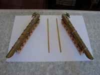
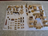
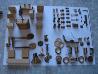
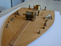
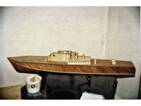
Joined modelboatmayhem as you suggested but unfortunately had no replies. Can anybody please advise where I can locate solid brass pins size 3mm x 0.3 diameter to save myself hours filing down larger. Enclosing a few shots of the boat built at a scale of 37.5/1 (crazy scale!!).
Hope the photos are ok. Bob Butcher ------------- Bob |
 Hi Christian,
Posted By: BLUEBIRD
Date Posted: 04 March 2008 at 12:16pm
|
hi ya there Bob the pins you require - are they similar to what we class as brass building pins - i.e. small nails for nailing the planking? or, are they some other type of 'straight' pin - I have been looking at the dimensions of the pins you require (3mm long by 0.3 diameter) is very very small diameter. I was thinking could you use a nikel plated dress making pin? but, I have just checked the diameter of those & they are 0.6mm diameter. I myself use a Company in the UK - its called E.K.P. Supplies their address - The Old Workshop, Bratton Fleming, Nr Barnstable, North Devon, EX31 4SA - telephone - U.K. - 01598 710892. They are also on the web if you do a google search on the web. I buy a lot of 1.00 mm diameter nuts and bolts from E.K.P. (as above) and they may be able to help you out with your pins. Good Luck. aye, John e, Bluebird
|
Posted By: rafwebfoot
Date Posted: 04 March 2008 at 1:06pm
|
Ref small brass pins. The best way to achieve these is to use copper wire. If you tap them in you will pein over the end slightly thus forming a'head'. I have used this method for many years to fix copper plates and veneer planking to models and they have never let me down. The smallest brass pins are 6mm long but the heads are not proportional to the dia. All the best. ------------- FAIR WINDS AND A FAVOURABLE TIDE Donald |
Posted By: Bob Butcher
Date Posted: 09 March 2008 at 4:39pm
|
Hi Rafwebfoot, Thanks very much for the tip, much appreciated, will give it a go. Bob ------------- Bob |